MEP ORAL -by harsha
MEP(MARINE ENGINEERING PRACTICE NOTES)
Check in exhaust valve for spindle rotation and spindle drop-down time check
A) check for exhaust valve spindle rotation:-
This check is carried out when engine was running. First pull up the indicator rod placed at the top of the exhaust valve and turn it to 90 degree and let it rest on air piston.
as the air piston moves the indicator will follow its movement. During rotation of the valve spindle, the top position of the indicator will change about 6 mm, because of the groove in the piston.
B) spindle drop-down time check:-
This test is carried out when engine is stopped
Engage all the rotation indicator on the exhaust valves.4
Shut off and release the spring air on the valve, next to the engine-side maneuvering stand.
Check the spindle drop time for all the valves:
Drop time witin 30 minutes : check and overhaul the valve and check for air spring tightness.
Drop time from 30 minutes to 1 hour : keep under observation.
Drop test above 1 hour : ok
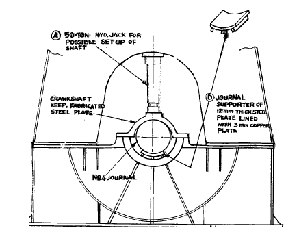
HOW TO CORRECT CRANKSHAFT SLIPPAGE
We have talked about how to correct the slippage in case the slip angle is less than 5 degrees. In this post we will talk about how to correct the slippage if slip angle is more.
Procedure :-
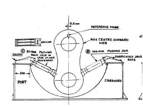
Before starting of the method mentioned below, con rod and main bearing of the unit should be taken out.
A) make a bracket from mild steel and secure it to the top flange of the bed plate. This will act as a buttress for the hydraulic jack.
B) make a metal tank from steel sheet of about 1 mm to surround the slipped side of crankshaft to put dry ice for cooling.
C) now in the figure above we can see that two jacks are used on either side. The advantage of using two jacks is that controlled movement of web will be taking place. And if web moves further then with the help of other jack, the web can be brought back to the corrected place.
D) a circular false bearing is fabricated and placed in place of main bearing with a 3 mm copper plate to save the journal. Above also a fabricated circular keep is placed.
E) now place a hydraulic jack from the top to secure the journal from movement when the side jacks will be pressurized.
F) now , a hole is drilled in crankshaft journal to pour liquid nitrogen. If crankshaft is having lube oil holes the plug the lower end with copper plug and then pour liquid nitrogen.
G) cooling of journal will shrink it.
H) now apply hydraulic force slowly to move the jack which will force the web to move. When the two marks on web and journal matches then stop applying pressure.
HOW TO CHANGE PMAX OF M/E OF ALL UNITS AT ONCE
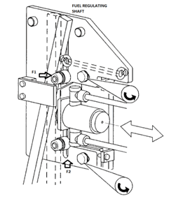
in earlier post how to adjust pmax of the individual cylinder we have discus changing pmax of engine of any individual cylinder. In this post we will discuss how to change pmax of engine of all cylinders at once. This is carried out by changing setting in the v.i.t system.
This adjustment is very fine till 2 degree advance or retard only. For this pivot valve f1 and f2 are axially displaced.
First release the screw and nut which secure the bracket with the pivot valve to the larger bracket through the slotted holes.
Increase in pmax is achieved by moving the pivot valve towards the lever.
Decrease in pmax is achieved by moving the pivot valve away from the lever.
AUXILIARY ENGINE LUBE OIL LEVEL DECREASING
Lube oil is required for proper cooling and reducing wear due to friction. Lube oil is normally consumed by some litres on a daily basis. It’s consumption should be monitored daily and a record must be kept. An increase in the lube oil consumption should be dealt immediately.
The reasons for lube oil level going down are as follows:-
The purifier is overflowing.
The suction valve to lube oil transfer pump is leaking.
L.o cooler leaking.
L.o leaking from l.o connection to fuel pump.
Sump doors are leaking.
L.o leaking from cylinder head.
L.o leaking from fuel valve nozzle cooling line to the fuel oil overflow tank.
L.o burning in cylinder due to worn out piston ring.
Oil leaking from l.o pump flange and pipe connection.
AUXILIARY ENGINE LUBE OIL LEVEL INCREASING
Lube oil is consumed slowly when the engine runs. But its level increasing is a problematic situation. Sometimes you may think its increasing if the dip stick is situated at the back, and the ship is trimmed aft. If this is not the case, then there can be other reasons as follows :-
A) maybe the lube oil filling valve is leaking.
B) fuel oil may be leaking inside the crankcase.
Fuel pump might be leaking.
Fuel valve leaking
Attached fuel pump seal leaking.
C) water might be leaking.
Water may be leaking from the cylinder cooling water system.
L.o cooler leaking (only when engine is not running)
The seal of h.t water pump leaking.
AUXILIARY ENGINE L.O PRESSURE LOW
L.o pressure is essential for efficient working of the engine. It helps to maintain an oil wedge between the bearings and the crankpin and journal.
l.o pressure is good when the engine oil is new and the filters are renewed. But as the engine’s running hours increase, the l.o deteriorates and the filter will chock slowly leading to decrease in l.o pressure. But there are other abnormal factors also too, these are :-
Decrease in l.o level in sump.
L.o pump relief valve leaking.
L.o cooler chocked.
L.o line chocked.
L.o line damage.
Nozzles inside the sump to lubricate and cool the gear drive worn out.
If piston cooling by nozzle is provided then check the spring. If too weak spring then it must be changed.
Bearing damaged. (CLEARANCE INCREASED)
Jacket water getting mix with l.o.
If nozzle cooling is by diesel oil , then if diesel oil leaks into sump it will decrease the l.o pressure.
The l.o pressure sensor may be faulty.
AUXILIARY ENGINE FAIL TO START ON AIR
Many times when we start an auxiliary engine, it fails to start. Starting problem in an auxiliary engine can be categories in two :-
A) not starting on air
B) starting on air but stop again
- In this post we will talk about engine not starting on air. Troubleshooting the problem should always be from the start.
- Check the air bottle valve whether it is open or not.
- Check the “y” filter for accumulation of oily slug.
- Adjust the air reducing valve.
- Check the main starting air valve actuation.
- Distributor may be faulty.
- The air line from distributor to starting air valves may be chock.
- Starting air valves might be sticky.
- In case you have an air motor starting, then check whether the pinion of air motor is getting engage properly with the flywheel or not.
- Check the air motor.
- With engines having constant pressure type turbocharger check the lambda controller.
HOW TO TAKE A TAPPET CLEARANCE
Tappet clearance is one of the most important clearance in a 4 stroke engine. It should be taken every month as clearance may change due to continuous running of auxiliary engine.
to take a correct tappet, the position of inlet and outlet valves is very important. The valves should be fully closed i.e the engine should be in compression while taking the tappet.
There are 3 ways to check that unit is under compression :-
The fuel cam should be at its peak.
The push rods of both the valves should be free to rotate.
The flywheel marking.
Out of all three the fuel cam at its peak is the best and most reliable. And it should be noted that tappet to be taken when the engine is cold.
Procedure to set the tappet :-
Rocker arm to be removed from place.
The bridge/yoke placed at the inlet and outlet valves are removed from place and the screw provided on the bridge/yoke is loosened.
Then we have to first adjust the clearance at the two ends of each bridge so that it is same for both the valves for each bridge/yoke i.e both inlet or exhaust valves must open simultaneously and equally.
This can be done by the help of a dial gauge and slowly rightning the screw on the bridge/yoke
Once done, then rocker arm is placed back and tightening screw is loosened after loosening the tightening screw nut.
Place the filler gauge of required thickness on between the bridge and the rocker arm.
Slowly tighten the tightening screw of rocker arm.
Feel the tightness of the feeler gauge. If ok then lock the locking nut and then repeat for the other valve.
Once done for all units, rotate the flywheel to check proper operation.
Advertisements
AUXILIARY ENGINE FAIL TO START ON FUEL
Continuing from the previous post , now let us see why the engine starts on air but fail to start on fuel.
As i said earlier also, lets start from the starting:-
- The quick closing valve may be closed.
- The fuel oil filter may be chock.
- Air in the fuel oil line.
- The pump plunger barrel may be sticky.
- The rack of fuel pumps may be sticky.
- Relief valve of fuel oil line of that particular generator may be leaking heavily.
REASON FOR HIGH EXHAUST TEMPERATURE
During daily rounds of the engine room, checking the exhaust temperature is a normal and most important observation. It tells the working condition of the engine and any possible deviation may point towards possible problem in the system.
If the exhaust temperature increases then it may be due to following problems :-
A) when exhaust temperature of only one unit increases :-
- Tappet clearance increases.
- Exhaust manifold got chock.
- Increase in piston clearance leading to blowpast in decrease in compression pressure. Hence incomplete combustion and increase in exhaust temperature.
- Leaky exhaust valve
- Leaky fuel injector
- Fuel pump timing to be checked.
- In case of main engine, scavenge fire can also lead to high exhaust temperature.
- Fuel pump rack linkage more inside than normal
B) when exhaust temperature of all unit increases :-
- Turbocharger fouling.
- Air filter of turbocharger fouled.
- Air cooler chocked on water side.
- Air side fouled of air cooler.
- Fuel oil temperature decreases leading to problem in atomization.
- Governor problem.
HOW TO RUN ENGINE WITH BROKEN STAY BOLT
Stay bolts hold the engine together and keep them in compression. A loose/crack stay bolt will lead to serious vibration in the engine.
but in case the stay bolts get cracked and we have to run the engine then following steps are taken to run the engine safely :-
- If the engine end stay bolts i.e the one located ahead of 1st cylinder or the one located aft of last cylinder) is cracked, the cylinder pressure is reduced to 75% of pmax.
- If the stay bolts in between 1st and last gets crack, then reduce the pressure at both of the adjacent cylinders to 80% pmax.
- Cracked stay bolts should be renewed at first opportunity. In case of 1st and last stay bolts both the stay bolts (exhaust and maneuvering side) are changed.
EXHAUST TEMPERATURE OF ENGINE DECREASES
Exhaust temperature is one of the most important parameter of the engine and should be checked during every rounds as deviation from normal will give us prior indication of any problem that is manifesting itself.
Decrease in exhaust temperatures can be due to many reasons. Lets us divide them into 2 categories :-
A) when exhaust temperature of all unit decreases :-
Decrease scavenging air temperature for which one must adjust the bypass line.
B) when exhaust temperature of any single unit falls :-
- Air in fuel pumps and fuel valve.
- Fuel valve spindle sticking.
- Fuel valve chock.
- Suction valve in fuel pump defective.
- Fuel pump plunger sticking.
- Check that the rack of fuel pump is at place or not.
- Puncture valve stuck to open condition.
DETERMINATION OF LEAKY STARTING AIR VALVE
Starting air valve is fitted on the cylinder head of every unit to allow starting air to enter the cylinder when the engine is started. It is operated when the distributor sends operating air at the top of this valve according to the firing order.hence, it is closed in normal position. But what if this valve is leaking?
a leaky starting air valve is a major cause of starting air line fire and hence it’s detection is of utmost importance. But the problem is to find out which one of the starting air valve is actually leaking.
To find that out, following steps are taken:-
- the engine should be stopped.
- Propeller clearance to taken.
- Distributor pilot air to all the cylinder be cut out.
- Open the indicator cock.
- Give a start kick to engine.
- Note the unit from which the air comes out. That starting air valve is leaking.
HOW TO ADJUST Pmax OF THE INDIVIDUAL CYLINDER
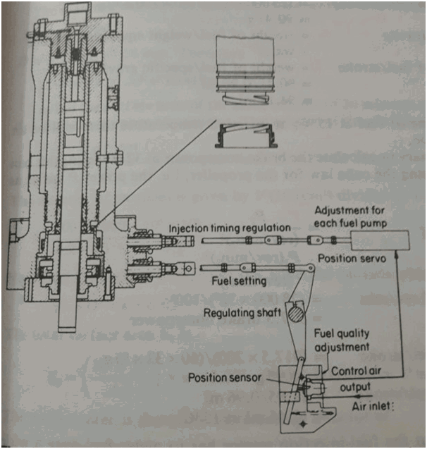
Pmax of the cylinder is the maximum pressure developed inside the engine. Vit controls the pmax of the cylinder unit. Hence to increase or decrease the pmax of the system we have to advance or retard the vit rack of the particular cylinder.
In the figure above we can see that vit is controlled by the servo cylinder which is actuated by the control air. Now to change the pmax, for individual cylinder we have to change the vit rack which is done by :-
- Moving the rack in/out
- To move the thread connection forward or backward.
-
INDICATION THAT BOILER TUBE IS LEAKING
Boiler’s are continuously subjected to high temperature and stress. It is always pressurized and steam is used for heating up of fuel. Due to high temperature, corrosion and other factors to tube may get weak and rupturing of tubes may happen.
Following are the indication for leaky boiler tubes:-
- The steam pressure of the boiler not increasing.
- Water level of the boiler and hot well not maintaining.
- Boiler smoke is white and flashes off as soon as comes out of the funnel.
- Water comes out of drain of boiler furnace.
REDUCTION IN CHEMICAL QUANTITY IN BOILER WATER:
https://meoexampreparation.wordpress.com/2017/07/10/how-to-remove-broken-stud/
M/E DOESNOT START WHEN TELEGRAPH IS SET TO START
Causes and remedies :-
- Any interlock is activated.
air pressure to low :- compressor to be started and check that they are working properly, also check whether air is leaking any where specially deck air.
Air bottle valve closed: - open the valve
Main valve closed: - set the main starting valve at service position.
Main starting valve is sticking closed position: - lubricate and mobilize piston and later overhaul the valve.
Valve at distributor closed: - open the valve for air to distributor.
No air pressure in pneumatic starting system :- clean the filter in the line and check the valves position.
Soleniod valve may be faulty.
CAST IRON CRACK REPAIR
https://meoexampreparation.wordpress.com/2017/07/09/cast-iron-crack-repair/
VACUUM IN FWG NOT DEVELOPING
Vacuum inside the fresh water generator is developed by the eductor which suck out the water and non- condensable gases out of the fwg to create the vacuum. This vacuum is required for the generation of water as in vacuum the boiling point of the water comes down. Hence creation of vacuum is must for water generation.
Reason for vacuum not developing are as follows :-
- Ejector pump filter got chocked.
- Ejector pump not creating pressure.
- Overboard valve not fully open.
- Eductor nozzle chock.
- Eductor nozzle worn out leading to increase in diameter of nozzle.
- Vacuum break valve leaking.
- Mechanical seal of distillate pump leaking.
- Tank filling valve closed.
- Extraneous matter in nozzle.
- Shell gasket is leaking.
- Salinometer 3 way valve leaking.
- The swing check valve on the suction line of the distillate pump chocked.
- Too high formation of non condensable gases due to high temperature of water.
SHORT CYCLING OF REFRIGERATION COMPRESSOR
Short cycling means continuous starting and stopping of compressor. There are following reason for short cycling :-
- Low pressure cut out faulty.
- Low pressure control difference too small.
- Wrongly adjusted capacity regulator.
- Suction filter chock.
- Refrigerant is low.
- Leaky refrigerant plant.
- Too much cooling water to condenser.
- Tev partially chocked.
- Tev bulb wrongly placed.
- Solenoid valve leaking.
- Frosting of evaporator coil.
- Defective piston ring or liner.
- Defective leaky discharge valve.
- Too high compressor capacity.
REFRIGERATION CONDENSER PRESSURE TOO HIGH
Normal cutting out pressure of refrigeration compressor for high discharge presure is normally 18 bar. But when the high cut out happens compressor do not start on its own. It has to be reset manually to start it again.
Reasons for high pressure in the system is due to the following reason :-
- Overcharge of refrigerant.
- Insufficient cooling water to condenser
- Temperature of cooling water high.
- Non-condensable gases in condenser.
- Condenser fouled.
- Water valve is not functioning properly.
- Load high on the system.
- Liquid entering to the system.
REASON FOR COMPRESSOR RUNNING CONTINUOUSLY
Compressor is one of the most important machinery on-board. Its maintenance is of prime importance for efficient running of the ship.
continuous running of compressor means the air bottle is not filling up and hence the compressor is not cutting out. It will lead to problems like valve damage, piston rung damage etc. Over all we can say the total maintenance hours decreases.
Reasons for continuous running are :-
- Suction and discharge valve are faulty and need to be replaced with an overhauled one.
- Inter-cooler and after-cooler are chock.
- Water flow in inter-coolers and after-coolers is not proper.
- Solenoid valves for unloading are leaking.
- Continuous usage of air.
- Air leaking in the engine room or deck.
- Relief valve of air bottle or the compressor are leaking.
- Any valve of air bottle is leaking, specially the drain valve..
FISH ROOM TEMPERATURE NOT DECREASING
One day while taking round, you found out that the temperature of fish room is not normal i.e its high. Now the question is how come other room temperature is normal while temperature of only fish room is high.
The reasons can be many but before going through detailing lets go inside the refrigeration room and check that out did our friend chief cook forgot to close the door of the fish room properly or not :p.
If door is ok, then check for following reason :-
- The evaporator coil is icy.
- Fan above evaporator coil is not working.
- Expansion valve is covered with ice.
- The solenoid valve might be faulty.
- Load on the fish can be more cause of more amount of stuff inside the room.
WHAT TO DO IF BURSTING DISC OF COMPRESSOR BURST DURING MANOEUVRING
Bursting disc is provided in inter-cooler to protect it’s casing in case inter-cooler line burst. Bursting of inter-cooler will make pressurized air to enter the casing and may lead to bursting of casing too. Hence to avoid it bursting disc is provide.
But what if bursting disc burst during manoeuvring? Well that’s a problematic situation. In this situation we cannot change the inter-cooler as air will be required frequently for main engine.
In this situation, the best way to handle the problem is by performing following steps :-
- keep the compressor in manual.
- One watchkeeper officer/ oiler should be present at all time to operate the compressor.
- Keep the water valves closed before starting the compressor.
- Once compressor is started, open the water valves and let the water flow out of the bursting disc area which is already open due to bursting of bursting disc.
- Keep an eye on the expansion tank of the compressor and fill it up as soon as the level start falling.
- Stop the water before stopping the compressor or else water will enter inside the inter-cooler tube.
FLAMEPROOF TEST OF ELECTRICAL EQUIPMENT
The requirement that the enclosure must also prevent transmission of any flame from an internal explosion to any explosive atmosphere surrounding the enclosure is tested by repeating the explosion test at least five times with the machine in a chamber, which is filled with the same explosive mixture. If the mixture in the chamber is not ignited, then the second set of tests is considered to have been passed & a flameproof ex d certificate is granted. Re-certification is needed for any modification of the casing.
Explosive mixtures vary in their ability to force flame through a gap of given dimensions; machines are grouped according to the design of the joint with respect to the length of the flame path, maximum gap & dimensions. Gases are generally listed for a given enclosure group.PISTON SEIZURE AND HOW TO REMOVE SEIZED PISTON
Seizure of piston inside the liner is caused by the piston rings getting stuck with the liner.
This is caused due to various reasons :-
- Taking out the piston out of the liner without cleaning the liner from carbon.
- Taking out the liner without taking out the anti-polishing ring out first. While taking out the piston rings get stuck on anti-polishing ring as its inner diameter is slightly less than liner inner diameter.
- In case of instantaneous stopping of engine.
Taking out the stuck piston is difficult but can be done by following ways:-
- Cooling the piston with the help of liquid nitrogen if available which will contract the piston and rings and piston will come out.
- A hydraulic jack is placed below the rod and jack is forced up leading to jacking up of piston.
- Piston rings are drilled out by the help of special fine drill and rings are broken. Then the piston can be taken out.
- If we have to run the engine and the piston is not coming out then we have to take the liner out along with piston and new liner and piston have to fitted. (normally every ship have a spare liner and piston. It is a minimum critical spare which has to be there onboard.)
LINER SEIZURE WHILE REMOVING AND REMEDY
Taking out cylinder liners are not something which we come across daily. Modern liners have long running hours and material used to make these liners is ” tarkalloy” which do not wear easily.
Removal of liners for renewal or to change the o-rings of water jacket is not a curb-some issue until its seize to come out. Seizing of liners is basically due to the o-rings getting jam inside its groove which are placed in liners to stop water leakage from the cylinder jacket. The o-rings may get jam if there previously an oversize o-ring has been used or the grooves were not cleaned before putting the liner back previously or due to slug formation around the o-rings.
While taking out the liner, the overhead crane should be moved up slowly so as to check whether the liner is coming freely or not. If its not free then not in any case the crane to be moved up as it will exert excessive pressure on o-ring and its frove and it may happen that the groove may get damage.
In this case, hydraulic jacks are placed below the liners. The stuffing box area has a flat surface provided where these hydraulic jacks are placed and a small jacking up is done. This help in lifting the liner and make the o-ring out of its place and now liner can be lifted up.
COPPER COIN TEST
In order to determine whether the crosshead journal surface is adequately smooth, a large, edges coin may be drawn longitudinally along the journal. The coin is pressed slightly at an angle of approx 45° against the journal surface and is held transverse to the direction of movement. When coin is moved, no vibrations must be either heard or felt.
WIPING IN BEARING
This kind of damage manifest itself by parts of the overlay nd/ or white metal contact face being wiped out, so that oil grooves in extreme cases disappear.
Cause:-
Provided adequate oil supply has been maintained, the damage can always be ascribed to a too high degree of roughness of the crosshead journal surface. The cause of excessive journal roughness may be an original defect in workmanship, subsequent mechanical or corrosive damage of the surface during transportation, storage, or hard particles in the lube oil. The roughness can also arise later by corrosion during the operative period of the engine if the lube oil develops weak acids or if strong acid- anhydrides are added to it, which , when combined with water in oil develops acid.
Repairs on the spot :-
Slight damage can be repaired by light scraping. For example in the case of slight wiping of the overlay or the white metal in the wedge-shaped oil grooves, these can be re-established by means of a scraper. In general, it is recommended to replace damage shells.
The journal is polished on the spot with a hemp string and polishing wax. A clean, soft hemp string, possible braided , of about three quarters of an inch thickness is wrapped twice round the journal and is pulled to and from until the coin test proves the surface to be adequately smooth.
Polishing wax and gas oil forming an abrasive paste of a suitably soft consistency are to be applied to the hemp string at regular interval. Let the string travel slowly from one journal end to other during the grinding.
ACTION TO BE TAKEN IN CASE RECIPROCATING PART IS DAMAGED IN M/E
In case of some serious defect in piston, piston rod, connecting rod etc. Then its not possible to let these parts move as this will cause further damage. In such case if we have to run the ship till the next port following procedure is carried out.
Procedure :-
- Fuel is cut off by lifting and securing the roller guide.putting fuel pump out of action
- Put the exhaust valve out of operation to put the exhaust valve closed.
- Dismantle the starting air line. This is done by blanking the main line and control air pipe for the actual cylinder. In this case, the blanking of the starting air supply is very important , as otherwise the starting air will blow down the suspended engine component.
- Suspend the piston, piston rod and crosshead and take the connecting rod out of the crankcase.
- Lube oil to crosshead is stopped.
- Set the lubricator to zero delivery.
ACTION TO BE TAKEN IN CASE OF LEAKY CYLINDER COVER OR LINER
Leaky liners and cylinder cover are not something that happens often. It is rare but when occur can have serious trouble for engine and have to be tackled quickly. While the engine is running the presence of black color water in expansion tank is an indication that liner is leaking.
To find out which liner is leaking we can stop the engine and have to do under piston inspection . The presence of water in the under piston of the particular liner suggest that it is leaking. In case of cylinder cover if leaky from inside the observation will be the same.
Now the corrective action that can be taken in case we have to sail without overhauling the unit till we reach a port, compression and combustion both have to be stopped. This is because liner or cylinder cover is already damage and hence compression and combustion will cause more damage as liner or cover are already weak.
Hence first of all the fuel pump roller is lifted up and fuel is cut off from that unit.
PUTTING FUEL PUMP OUT OF ACTION
Now the exhaust valve is made to remain open by stopping the air spring air and to lift the exhaust valve actuator roller up. Oil inlet for actuator is blocked or pipe is taken out.
Starting air line is blanked.
The moving parts like piston and connecting rod are still opertional and cylinder lubrication and cross head and piston lubrication are still active and untouched.
ACTION TO BE TAKEN IN CASE OF BEARING FAILURE
In case of bearing failure, we need to replace the bearing with the new one. But this require time and the ship should be in a safe location where you can immobilize the ship for some period of time. The engine though may be run by lowering the load on the bearing. This is done by stopping the combustion.
To stop the combustion the fuel must be cut off by lifting the roller up from the cam.
putting fuel pump out of action
As the combustion is no more the load on the bearing will be reduced. The exhaust valve , lubrication to connecting rod and crosshead, starting air etc will be functioning normally. Athe piston, conecting rod and other moving parts will also be working normally.
HOW TO ADJUST CLEARANCE OF THRUST PAD
Adjustment is generally carried out on the ahead thrust pads because these pads are more subjected to wear due to the fact that ship moves ahead mostly.
The adjustment of clearance is done in following steps:-
- Removing the pad out.
- Then the screw on the back plate is removed.
- Now place shims between the back plate and the housing.
- The pads are then boxed back and clearance checked.
HYDRAULIC PRESSURE TESTING OF BUNKER LINE
Bunker lines are required to be tested to 1.5 times their allowable operating pressure by placing them under a constant hydrostatic load for a prescribed period of time (usually 5-10 minutes is sufficient). This is best achieved by using the fo transfer pump (s) to fill bunker lines up to the manifolds (with fuel oil), purge the lines via manifold valves, then build pressure in the lines until 1.5 times the normal operating pressure is reached (operating parameters should be available in the bunker plan, or the vessel may be guided by pipeline material pressure ratings).
If the fo transfer pump is a positive-displacement type, it may be stopped when the required test pressure is reached as it should not permit backflow. If a centrifugal type of pump is employed, constant running will be required to ensure the necessary pressure is maintained during the test. In addition to log entries in deck logbook and oil record book (orb), the deck bunker lines are also required to be stenciled with the date of last pressure test together with the pressure maintained (in kg/cm2, psi or bar).
THRUST BEARING CLEARANCE
For new engine the clearance is 0.5 to 1 mm. The maximum limit for the clearance is 2 mm.
A wear groove of 1 mm is positioned in the upper most thrust segment having a thermometer.
the thrust segment is pressed against thrust cam to eliminate any gap by the help of a crowbar and a feeler gauge of 0.1 mm is put inside the groove. If it does not go inside that means wearis more than 0.9 mm. Hence the bearing has to be overhauled.
HOW TO PUT TURBOCHARGER OUT OF OPERATION
Turbocharger is a very high speed machinery. Any trouble while running can cause serious damage to the turbocharger and hence early step should be taken to avoid such damage.
Turbocharger can be put out of operation, by following the steps given below.
Condition 1 :-
The ship must be instantly manoeuvred:- reduce the load until the vibration cease.
The ship must be instantly manoeuvred but the damage to turbocharger is such that it cannot be run at low load :-
This mode of operation is to be carried out if you have to run the engine for small time.
If engine has only 1 turbocharger :-
Stop the engine.
Lock the rotor of the turbocharger.
Remove the compensator between the compressor outlet and the suction air duct. It decreases suction resistance.
Load to be reduced
2. If engine has 2 turbocharger with 2 or more turbocharger :-
Stop the engine.
Lock the rotor of the turbocharger.
Insert an orifice plate in compressor outlet. A small air flow is required from compressor to cool the impeller.
Load to be reduced.
Condition 2:-
Putting the turbocharger out of operation for extended period
1. Engine with one turbocharger and exhaust bypass :-
Stop the engine.
Lock the rotor of the turbocharger.
Remove the blanking plate from exhaust bypass line
Remove the compensator between the compressor outlet and the suction air duct. It decreases suction resistance.
Load to be reduced
2. Engine with one turbocharger and no exhaust bypass :-
Stop the engine.
Remove the rotor and nozzle ring of the turbocharger.
Insert blanking plate.
Remove the compensator between the compressor outlet and the suction air duct. It decreases suction resistance.
Load to be reduced
3. If engine has 2 turbocharger with 2 or more turbocharger :-
Stop the engine.
Lock the rotor of the turbocharger.
Insert an orifice plate in compressor outlet. A small air flow is required from compressor to cool the impeller and to prevent corrosion.
Load to be reduced.
METAL ARC WELDING
The principle of metal arc welding consist of establishing an electric arc between a metal electrode and the work piece to be welded.
Arc can be described as a stream of incandescent vapor which acts as a conducting medium for electric current from one terminal to another to complete the circuit.
The electric current has fairly high voltage to overcome the extra resistance offered by the vapor.
Function of flux :-
to produce a gas which provides a shield around arc to protect it from atmosphere.
forms slug by mixing with the impurities of molten metal and thus refining the metal.
slag floats over the molten metal and solidification forms a thin layer which help in gradual cooling of weld and prevent its oxidation during cooling
Control bead shape by providing necessary materials for this purpose.
Arc blow :-
It is the distortion of arc which lead to bending of the arc away from its intended path is called arc blow. Mainly found in dc welding as there is fixed polarity, the induced magnetic field are constant in direction. Mainly found during starting and end of weld.
Use of ac welding :-
In ac welding, step down transformer reduces voltage from 440 volts to 80-100 volts.
This voltage is required only to start the arc and for maintaining the same we require 30-40 volts.
This is accomplished by current regulator, through whcih we can adjust flow of current and also resistance and hence can obtain the desired voltage.
Since in ac, it passes 0, twice in every cycle hence voltage is 0 at this point, hence higher voltage is required.
Use of dc welding :-
Voltage is 60-80 volts to strick the arc and 15-25 volts to maintain it.
Positive terminal- heat developed should be 2/3
Negative terminal- heat developed should be 1/3
Straight polarity – electrode is negative and work piece is positive
Reversed polarity – electrode is positive and work piece is negetive.
Due to these polarities , almost all metals can be welded by using dc welding as many metals require more heat to acquire the fusion state than the electrode used. Example :- copper.
Difference between ac and dc welding :-
- ac is cheaper and easily maintained than dc.
- preferred for welding at large distance from supply because voltage drop is less while dc welding is used for shorter distance.
- Striking arc is difficult in ac.
- Ac is not preferred for welding sheets while dc is preferred.
- No arc blow in ac .
- Ac is not suitable for non ferrous metals while we can weld non ferrous metals with dc.
OXY- ACETYLENE WELDING/CUTTING
Advantage of using acetylene instead of other fuel is that it produces a comparatively higher temperature and also an inert gas envelop, consisting of co2 and h2o which prevents molten metal from oxidation. The maximum flame temperature is 3200 degree celsius.
Equipment :-
oxygen is contained in a black color cylinder of 125 kg. It has a brass/ copper connector and is having a right hand thread.
Acetylene is contained in a maroon color cylinder of 21 kg. It has a iron connector and is having a left hand thread.
This is the difference which one can see to find out which cylinder in which if they are not marked.
Acetylene cylinder carries a porous mass inside, soaked in acetone which has a capacity to dissolve 25 times of its own volume of acetylene for every atmosphere of pressure applied. Acetylene is compressed into these cylinder so as to dissolve in acetone and that is why it is called “dissolved acetylene”.
Nozzle tip is interchangeable. Different size of tips enable the operator to select a suitable one to obtain the desired size of flame that will suit the particular thickness of metal to be welded.
Size of orifice control the flow of gas mixture.
Small orifice- smaller flame, large orifice- larger flame.
Pressure regulator is provided at every cylinder which carried a reducing valve.
Borax and naco3 are the flux used.
Safety in the system :-
- flash back arrester between regulator and hose.
- Non return valve in the oxy-acetylene torch.
- Fusible plug
Type of flames :-
- Oxidising flame– for brass.
- neutral flame – for cast iron, mild steel, stainless steel, copper,aluminium, nickel, monel metal.
- Carburizing flame – lead
Oxy- acetylene cutting :-
It is a chemical process in a sense that metal, at the portion where it is to be cut, is actually made to oxidise under the action of flame.
Metal to be cut is heated up to red heat by means of flame and then a sharp stream of oxygen is made to impinge on to the hot surface to form iron oxide and thus remove metal from there.
Melted iron oxide get blown off by the jet of oxygen, thus providing a narrow slit along the cutting line.
6 mm distance to be maintained between tip and metal.
Spark should come from other side of the plate.
Normally neutral flame is used but for cast iron, carburizing flame is used and that too at a comparitively larger distance.
GEAR PUMP OVERHAUL
- Switch off the breaker and take out the fuse.
- Place men at work board.
- Isolate the pump by closing suction and discharge valve.
- Open the vent valve to check that valves are holding.
- Motor electrical connections to be removed.
- Mark on couplings with permanent marker.
- Take out the coupling bolts of pump and motor.
- Disconnect suction and discharge flanges
- Remove foundation bolts.
- The shims below pump should be removed and placed acc to their location so that they can be placed back in correct position.
- Suction and discharge line to be covered with clothes.
- Take pump to workshop.
- Take the coupling out by bearing puller.
- Remove key of coupling
- Remove end covers on both side.
- Remove mechanical seal.
- Remove the locking nut on other end and the bearing.
- Take out the gear shaft along with bush.
- Remove the relief valve cap at top and take out relief valve spring and seat.
- Clean all parts and carry out inspection.
- Check gear for wear, backlash, damage.
- Bearing to be check for unsual noise and damage.
- Check bush and shaft clearance.
- Check gear shaft for grooving mainly where seal sits.
- Check clearance between casing and gear.
- Check relief spring tension.
- If everything is ok then start boxing back with new gaskets for end covers. Gaskets to be made of paper mostly.
- Bearing to be renewed.
- Mechanical seal to be renewed.
- Box back the pump.
- When placing the pump back on place. First put the shims on correct place.
- Then the coupling bolts and check the alignment.
- If alignment is ok then tighten the foundation bolts or else adjust the shims.
- Tight the suction and discharge bolts and nuts.
- Open the suction valve and purge the pump.
- Open the discharge valve.
- Make electrical connections and put fuse back.
- Switch on the breaker.
- Start and stop the pump to check the direction of rotation.
- If ok then pump can be put in operation.
CENTRIFUGAL PUMP OVERHAULING
- SWITCH OF THE BREAKER AND TAKE OUT THE FUSE AND KEEP IT IN A SAFE PLACE. PLACE MEN AT WORK BOARD.
- CLOSE THE SUCTION AND DISCHARGE VALVE OF THE PUMP TO BE OVERHAULED.
- REMOVE THE SUCTION AND DISCHARGE PRESSURE GAUGE CONNECTION TO CHECK WHETHER THE VALVE IS HOLDING OR NOT.
- REMOVE THE ELECTRICAL CONNECTION OF THE MOTOR AND MARK THE CONNECTIONS APPROPRIATELY.
- NOW THE PROCEDURE WE WILL BE DISCUSSING IS FOR TOP COVER TYPE.
- MARK THE MOTOR TO THE BODY AND COUPLING AND TOP COVER AND BOSY WITH PERMANENT MARKER.
- REMOVE THE COUPLING BOLTS BETWEEN PUMP AND MOTOR SHAFT.
- TAKE OUT THE MOTOR AND PLACE IT ON FLOOR AND SECURE IT.
- REMOVE ALL NUTS FROM THE TOP COVER OF THE PUMP.
- WITH THE HELP OF CHAIN BLOCK OF REQUIRED SWL AND WIRE SLING, TAKE THE PUMP SHAFT OUT.
- TAKE THE PUMP TO WORKSHOP AND COVER THE PUMP OPEN COVER WITH CLOTH .
- UNLOCK THE LOCKING PLATE AND REMOVE THE IMPELLER NUT.
- TAKE THE LOCKING PLATE OUT.
- REMOVE THE IMPELLER WITH THE HELP OF BEARING PULLER BUT FIRST CHECK THE DIRECTION OF THE IMPELLER BLADES.
- TAKE OUT THE IMPELLER KEY OUT AND WASHER PLACED BEHIND THE IMPELLER.
- NOW PUSH THE SHAFT OUT FROM THE OTHER DIRECTION.
- NOW CLEAN THE SHAFT AND REMOVE THE MECHANICAL SEAL. BUT BEFORE TAKING OUT THE SEAL DO NOTE THE POSITION OF SEAL IN SHAFT BY THE HELP OF VERNIER CALIPER SO THAT NEW SEAL CAN BE PLACED IN THE CORRECT POSITION
- TAKE OUT THE GLAND COVER.
- CHECK THE CONDITION OF SLEEVE AND CHECK FOR GROOVES AND MARKINGS WHERE MECHANICAL SEAL IS FIXED.
- IF SLEEVE IS HAVING ALOT OF GROOVES THEN SLEEVE TO BE REPLACED.
- CLEAN THE IMPELLER, KEY, SHAFT AND TOP COVER.
- CHECK THE IMPELLER FOR CORROSION, PITTING, CAVITATION AND WEAR. CHECK CONDITION OF IMPELLER BLADES FOR NARROWING.
- CHECK THE KEY FOR CRACK AND KEY WAY TOO.
- CHECK THE FOLLOWING CLEARANCES :-
- SLEEVE TO SHAFT – 0.03-0.04MM
- IMPELLER TO SHAFT – (METAL TO METAL FIT) 0.13MM
- WEAR RING CLEARANCES –
- STUFFING BOX THROAT BUSHING AND SHAFT
- IF CLEARANCES ARE OK THEN START BOXING BACK THE PUMP IN REVERSE DIRECTION.
- MAKE SHAFT CLEAN AND DRY. PUT GLAND COVER. PLACE NEW MECHANICAL SEAL IN THE EXACT POSITION AND LOCK IT KEEPING IT MIND THAT IN ALL SCREW POSITION THE SEAL IS AT SAME DISTANCE.
- STUFFING BOX TO BE CLEANED AND CHECKED FOR CLEAR PASSAGE FOR WATER.
- PLACE SHAFT ON THE TOP COVER.
- PUT WASHER IN PLACE AND THEN THE KEY.
- IMPELLER TO BE PLACED BACK AND LOCKED WITH LOCKING PLATE.
- TAKE THE PUMP TO PLACE AND BOX IT BACK.
- TIGHTEN THE TOP COVER NUT AND PUT MOTOR BACK IN PLACE.
- CONNECT THE COUPLINGS AND ROTATE THE PUMP TO CHECK THE FREE MOVEMENT.
- CRACK OPEN SUCTION VALVE AND PURGE THE PUMP.
- MAKE PRESSURE GAUGE CONNECTIONS.
- CHECK FOR LEAKAGE IN MECHANICAL SEAL
- MAKE MOTOR CONNECTION
- OPEN SUCTION VALVE COMPLETELY.
- START AND STOP THE PUMP TO CHECK THE PRESSURE BUILD UP IN PUMP AND TO CHECK THAT PUMP IMPELLER IS PLACED IN CORRECT DIRECTION.
- IF ALL OK THEN START THE PUMP AND SLOWLY OPEN THE DISCHARGE VALVE TO PUT THE PUMP IN OPERATION.
STAY BOLTS TIGHTENING
- Remove the protective cap of the stay bolts.
- Check the loose stay bolt nut by the help of the tommy bar. If loose nut is found then unscrew the nut until a gap occurs between the cylinder frame and the nut.
- Loosen and unscrew the nut on the opposite stay bolt.
- Check the length of the bolt from head to the cylinder frame. If the length is no reached that means stay bolt is not properly screwed on the bed plate.
- Apply the screw and the counter nut in the thread in the top of the stay bolt and turn the stay bolt until that required length is reached.
- Retightened the bolts in pairs in athwart direction from fore to aft.
- Clean the contact face and mount the hydraulic tool on the pair of stay bolt positioned opposite to each other.
- Connect hydraulic pump by hose and 2 stay bolts are tightened in one operation.
- Maintain the pressure and use tommy bar to tightened the stay bolt nuts. Before relieving the pressure check by feeler gauge that nut bear to contact faces.
- When all stay bolts are retightened, connect hydraulic tool to the first pair of stay bolt tightened.
- Tightened below 10% of the tightening pressure and check that the stay bolts are loose or not.
- If stay bolts are not loose then tighten the stay bolts concerned to the mounting pressure.
- If stay bolts are loose then repeat the process.
- After completing the tightening then put the protective cap back.
LIFEBOAT DAVIT MAINTAINANCE
Following maintainance should be done on lifeboat davit :
1. Frame :-
Check corrosion , deformation and depression weekly and monthly.
2. Davit arms :-
Check corrosion, deformation and depression weekly and monthly
Check operation by moving and turning out from stowed place weekly and monthly.
3. Sheave , suspension block :-
Check wear and corrosion monthly.
Check moving condition weekly and monthly.
Lubricate/ grease weekly.
4. Hinge pin :- lubricate monthly.
5. Davit arm stopper and trigger block :-
Check wear and corrosion weekly and monthly.
Check moving operation weekly and monthly.
Lubricate monthly.
6. Boat fall and turn buckle :-
Check wear, brokage of wire and corrosion.
Lubricate/ grease monthly.
Turn ends of boat fall every 2.5 years.
Replace boat fall every 5 years.
7. Lashing wire rope :- check for corrosion, wear and looseness.
8. Boat chock:- check wear and corrosion.
9. Gear box, gear,bearing, oil seal:-
Check lube oil level and condition of oil.
Check for unusual noise during operation.
10. Brake system :- check corrosion or any other defect.
11. Wire end cotter :- check looseness.
12. Brake lever :-
Check corrosion or any other defect.
Check operating condition.
OVERHAULING OF CYLINDER HEAD
- Cylinder head overhauling is the most basic overhauling that is carried out onboard. When cylinder head is taken out from the auxiliary engine it is taken to the workshop. Following procedure is carried out for cylinder head overhauling:
- first of all, remove the split cotter and springs.
- take out the inlet and outlet valves.
- clean the cylinder head thoroughly in chemical to removed all carbon. Drain the chemical and blow air.
- When cylinder head is dry then inspect the cylinder head for any damaged in seat. Damaged seat to be removed and new seat to be installed.
- Inlet and exhaust vales are also inspected after cleaning for any crack and pitting and signs of cut mark. If cut mark is there than new valve should be used.
- The valve guide to be inspected for clearance. If clearance is more than valve guide to be removed.
- springs should be inspected for spriing action.
- valve rotator to be opened. Balls to be checked for flatness and belevelle washer to be checked for deep ball marking in washer as it will restrict the motion of the valve rotator. Renew ball and washer for efficient operation.
- in case pitting is presence in seat and valve then lapping is carried out. But care to be taken that the valve and seat angle doesnot exceed the valve in the manual as it will lead to shrouding.
- new seat and valve guide should be first cooled in refrigeration room and then shrunk fit on its place.
- Fuel valve area to be thoroughly cleaned.
- Pressure testing of cylinder head is carried out to inspect that cylinder head doesnot leak water when fitted in place.
Pressure testing of cylinder head :-
All the opening underside of head is blanked. On the top of the head all opening except one is blanked. Now pour water inside the head till it fills up completely. Now connect the hand pump on the opening and pump water inside the head till pressure in pressure gauge shows 4-6 bar pressure. Let it hold for 30 minutes. Check for signs of water leakage from all the opening and tight it if leakage is there, again raise the pressure if pressure had drop due to leakage from openings blanked. Also check for leakage from any other area specially exhaust valve seat, fuel valve area , side covers of jacket and underside of jacket. If leakage from cylinder jacket is there than open the jacket and renew the o-ring. Again do pressure testing to check the leakage.